Trailer Wiring Diagram - Trailer Rebuild: Designing A 12V Setup | Intents Offroad - You can be assured that we have the right parts to suit your.
Dapatkan link
Facebook
X
Pinterest
Email
Aplikasi Lainnya
Trailer Wiring Diagram - Trailer Rebuild: Designing A 12V Setup | Intents Offroad - You can be assured that we have the right parts to suit your.. Not sure which wires attach to what on your trailer connectors? Standard load trail trailer electrical connector wiring diagrams note: Our trailer wiring diagram is a colour coded guide designed to help you wire your trailer plug or socket. Detailed coloured12n trailer wiring diagram which is commonly used on uk and european trailers and caravans from western towing. This type of connector is normally found on utvs, atvs and trailers that do not have their own braking system.
Home > useful information > wiring diagram. Boat trailer color wiring diagram. Standard electrical connector wiring diagram. This color trailer wiring diagram will help you when you need to connect your trailer to your truck's wiring this diagram shows the colors of a basic trailer wiring setup as well as what each wire is. Standard load trail trailer electrical connector wiring diagrams note:
Building Tiny House on Flatbed Trailer and Need Brake ... from www.etrailer.com Trailers are required to have at least running lights, turn signals and brake lights. Not sure which wires attach to what on your trailer connectors? This is a short video series of the steps that i have taken to refurbish and old utility trailer that was designed and built by my father. Does one of your turn signals not work and you're not sure which wire to inspect? Anyone have a wiring diagram for the trailer hitch harness? Home > useful information > wiring diagram. Can also be used as custom wiring on trailers with 3 light/wire systems. Identify contacts by looking into the open end of plug or socket.
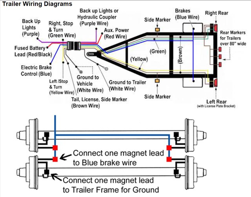
Not all trailers/vehicles are wired to this standard. Use on a small motorcycle trailer, snowmobile trailer or utility trailer. This is a short video series of the steps that i have taken to refurbish and old utility trailer that was designed and built by my father. We recommend these standards because they are pretty universal. This color trailer wiring diagram will help you when you need to connect your trailer to your truck's wiring this diagram shows the colors of a basic trailer wiring setup as well as what each wire is. You rely on your trailer day in and day at trailer superstore, we understand trailer wiring can be frustrating, and you may not know. Standard electrical connector wiring diagram. Standard load trail electrical connector wiring diagrams. Our trailer wiring diagram is a colour coded guide designed to help you wire your trailer plug or socket. A brake controller has only one output wire. If that wire runs to one wheel, then the other, then the other and the other as demonstrated above. I want to wire up some side marker lights and think it would be best to wire into this than the underhood box plus the wires would be easier to get to. Standard load trail trailer electrical connector wiring diagrams note:
Standard load trail trailer electrical connector wiring diagrams note: Trailer wiring diagram, trailer brake light plug wiring diagram, electric trailer brakes, hitch lights, 7 pin, 7 way, 7 wire, 6 pin, 6 way, 6 wire, 4 pin, 4 way, 4 wire, connector, connection, utility, horse. A brake controller has only one output wire. The following trailer wiring diagram(s) and explanations are a cross between an electrical schematic and wiring on a trailer. Not sure which wires attach to what on your trailer connectors?
Trailer Wiring Diagrams | etrailer.com from www.etrailer.com The above are to australian trailer wiring standards. This color trailer wiring diagram will help you when you need to connect your trailer to your truck's wiring this diagram shows the colors of a basic trailer wiring setup as well as what each wire is. The use of an electrical circuit tester is recommended to ensure proper match of vehicle's wiring to. Can also be used as custom wiring on trailers with 3 light/wire systems. 1st august 2017 by western towing. Detailed coloured12n trailer wiring diagram which is commonly used on uk and european trailers and caravans from western towing. Standard load trail electrical connector wiring diagrams. Not sure which wires attach to what on your trailer connectors?
Use this as a reference when working on your boat trailer wiring.
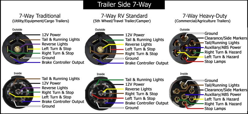
Australian trailer plug & socket wiring diagrams. Trailers are required to have at least running lights, turn signals and brake lights. Standard load trail trailer electrical connector wiring diagrams note: Can also be used as custom wiring on trailers with 3 light/wire systems. Cm trailer equipment are a leading distributor of high quality trailer parts and components to the light trailer building industry in new zealand. The following trailer wiring diagram(s) and explanations are a cross between an electrical schematic and wiring on a trailer. 1st august 2017 by western towing. Use this as a reference when working on your boat trailer wiring. 7 wire trailer circuit, 6 wire trailer circuit, 4 wire trailer circuit 7 wire circuit trailer wiring diagram. Identify contacts by looking into the open end of plug or socket. Use on a small motorcycle trailer, snowmobile trailer or utility trailer. The above are to australian trailer wiring standards. This is a short video series of the steps that i have taken to refurbish and old utility trailer that was designed and built by my father.
Bike to trailer wiring diagram. A brake controller has only one output wire. Not sure which wires attach to what on your trailer connectors? The wiring schematic that we use is: Our trailer wiring diagram is a colour coded guide designed to help you wire your trailer plug or socket.
Diary of A Handyman from 4.bp.blogspot.com Are now using 5 wire flat plug wiring to be more compatible with 4 and 5. Boat trailer color wiring diagram. 4 pin trailer wiring diagram. Trailer wiring diagram, trailer brake light plug wiring diagram, electric trailer brakes, hitch lights, 7 pin, 7 way, 7 wire, 6 pin, 6 way, 6 wire, 4 pin, 4 way, 4 wire, connector, connection, utility, horse. From 4 pin flat to 7 way round connectors. This color trailer wiring diagram will help you when you need to connect your trailer to your truck's wiring this diagram shows the colors of a basic trailer wiring setup as well as what each wire is. Detailed coloured12n trailer wiring diagram which is commonly used on uk and european trailers and caravans from western towing. Standard electrical connector wiring diagram.
This is a short video series of the steps that i have taken to refurbish and old utility trailer that was designed and built by my father.
Or why not make your diy installation easier with our 'plug and play' solutions. The following trailer wiring diagram(s) and explanations are a cross between an electrical schematic and wiring on a trailer. This article shows 4 ,7 pin trailer wiring diagram connector and step how to wire a trailer harness if you follow our trailer wiring diagrams, you will get it right. You can be assured that we have the right parts to suit your. If that wire runs to one wheel, then the other, then the other and the other as demonstrated above. From 4 pin flat to 7 way round connectors. The above are to australian trailer wiring standards. Trailers are required to have at least running lights, turn signals and brake lights. Standard load trail trailer electrical connector wiring diagrams note: A brake controller has only one output wire. Are now using 5 wire flat plug wiring to be more compatible with 4 and 5. Diagrams are looking from the outside of the plug or socket. 4 pin trailer wiring diagram.
All Star Tower Defense Codes 2021 - Brawlhalla codes October 2020: Talon Scythe, Raven Espada ... / Whether you are a fan of bodybuilding games or just want to adopt a few pets, there is something for everyone out there. . All star tower defense codes (working). What are the new all star tower defense codes and also how you should claim the free gems ? You've come to the right spot. All star tower defense active codes. Here, you play as a character with increasingly powerful powers and faculties, leveling up to defeat your opponents. They will help you to destroy enemy towers quickly. All star tower defense is one of the most popular tower defense games in the roblox ecosystem. All star tower defense codes (expired). There's many different types, so many people are familiar with this format. All of coupon codes are verified and tested today! All Star Tower Defense Codes 2021 | St...
2004 Vw Gti Engine Diagram : Volkswagen 1 8t Engine Diagram - Complete Wiring Schemas / For further details, or for information on current or new vw engines not listed here, please consult your local volkswagen dealer. . The north america mkvii gti is a very new car, assembled in a new way in a new factory with a new engine so it could mean trouble. Engine volkswagen fox 2004 workshop manual. 2) remove camshaft position sensor, o ring. It has proper section bookmarks and can be searched with a *note: Project vw mk4 gti 1.8t. What you see here is a 2004 mk4 gti 1.8t with cloth interior, sunroof, and roughly 125,000 miles on the odometer. Vw transporter t5 2004 электрооборудование (ru). For further details, or for information on current or new vw engines not listed here, please consult your local volkswagen dealer. Polo, golf, jetta, new beetle. Engine volkswagen fox 2004 workshop manual. 2...
Mark Levinson Lexus Lifier Wiring Diagrams - Lexus LS460 Mark Levinson No Audio - YouTube - We've all read the sob stories. . Does it go into protect? W/o active stabilizer suspension system. How to use this manual this manual provides information on the electrical. 26th february 2014 01:23 am. Amplifier mark levinson n38 operating manual. 2004 lexus es330 sedan navigation mark levinson sound system. But for now, we have lexus and the mark levinson sound system. I have three blue/yellow wires under there.) can anyone point out what's i already ran a set of 9 wire to the amp area from the hu and the hu is all connected apart from speakers. My mark levinson amp died. Wiring diagrams, spare parts catalogue, fault codes free download. I Recently Purchased a 2004 Lexus LS 430 with GPS and the ... from ww2.justanswer.com Provides circuit diagrams s...


Komentar
Posting Komentar